Purpose
Define the different types of drag loads that may impact a truss.
Steps
1. Click Component > Drag Load.
The Drag Load dialog displays.
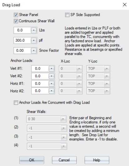
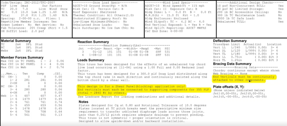
- Shear Panel - create shear panels; also, bevel the top chords of shear panels to the roof pitch and stack a block on the top of a shear panel. This setting reduces the load combinations to only those including drag load. Therefore, the component will not be designed for any loads other than drag load and dead load, as required in the ASCE 7 load combinations; all other load types will be ignored. See Create Shear Panels in Design View and Create Shear Panels & Blocks in Layout.
- Continuous Shear Wall - enabling this option allows the shear load (drag load) to be spread out along the length of the bottom chord.
- SP Side Supported - shear panels may be defined as side supported to minimize reactions at the bottom. The reaction is spread along the end verticals in the truss on either side, as noted on the engineering.
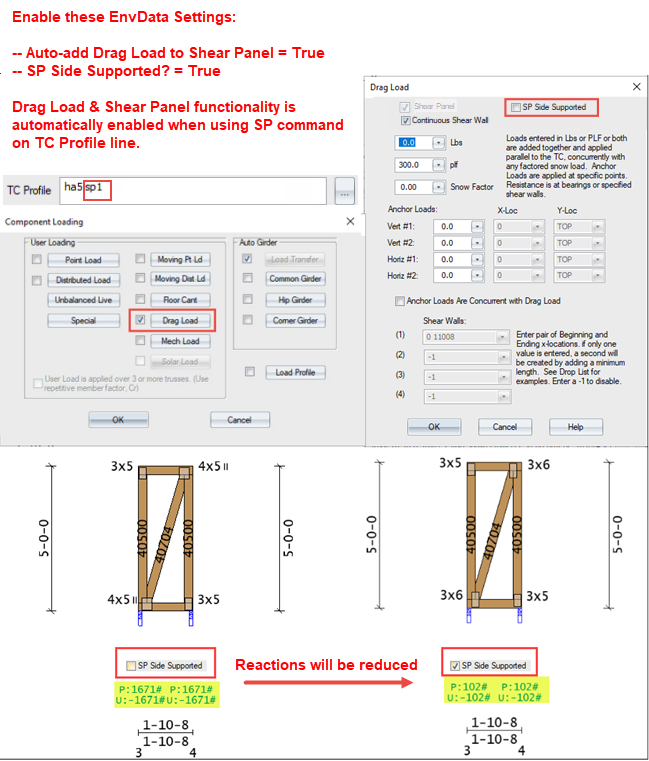
When you select the SP Side Supported option, the following notes display.
- Lbs - total drag load to be applied, in pounds to the current truss. Entries here are converted to PLF, but are shown as LBS in the window.
- PLF - pounds per linear foot drag load to be applied to the current truss
Note: Both Lbs and PLF entries may be used simultaneously, but everything is converted to PLF for application to the truss. If both types are entered at the same time, they will be combined into the same load cases.
- Snow Factor - allows a percentage of snow load to be used with the generated load cases. Per building code, anything over 30 PSF snow requires 20% of the snow load to be included. Note that the Snow Factor setting is intended for drag trusses (not shear panels) when the construction documents require a certain percentage of snow load to be applied concurrently with drag loads; however, it is best to check with the EOR or Building Designer if the construction documents are not clear regarding specific loading requirements for these components.
- Anchor Loads - additional point loads added to drag load combinations at specific points. For example, sometimes there are towers or other apparatus attached to trusses, that introduce point loads that are downward at one location and upward at the opposite side; and sometimes, they are accompanied by a shear (horizontal) load. Sometimes the horizontal load is from a brace that has two points of contact: one is generally on the top chord, and the other could be on a parapet wall or on a different truss. These are technically drag loads, because they apply in different directions depending on the direction of motion, like drag loads applied along the chords. These anchor loads may or may not be applied simultaneously with "regular" drag load.
- Vert #1 and Vert #2 - enter up to two vertical point loads, magnitude specified in the first box, at x-locations specified in the second box, and y-locations specified in the third box. The y-location box options include TOP = top chord, BOT = bottom chord, WEB = web.
- Horiz #1 and Horiz #2 - enter up to two horizontal point loads, magnitude specified in the first box, at x-locations specified in the second box, and y-locations specified in the third box. The y-location box options include TOP = top chord, BOT = bottom chord, WEB = web
- Anchor Loads are Concurrent with Drag Loads - indicates whether the specified anchor loads are combined with the specified Lbs and PLF drag load, or treated independently.
- Continuous Shear Wall - when checked, this option enters a full-panel shear wall description in the #1 shear wall box.
- Shear Panel - indicates that the truss being designed fits between trusses over a shear wall, and extends the shear wall up to the roof diaphragm.
Note: Drag note labels display in the model space when EnvData > LayoutSettings > Labels > Display Drag Note is set to True. See Label Settings.
3. Click OK to save changes.
4. On the Component Loading window, check the Drag Load box, then click OK to apply your changes.